Compatible LEDs & Wiring Guide
Supported Types
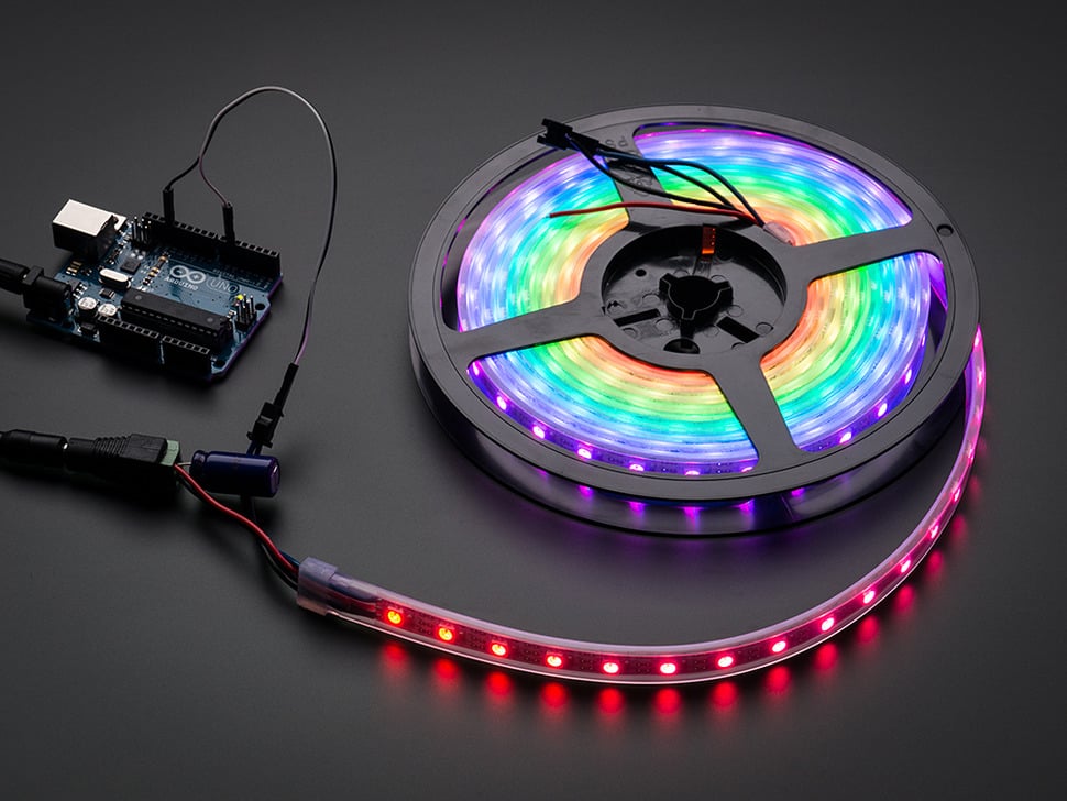
WS2812 / NeoPixel Strips
The most common smart LED strips, each LED independently controllable. Ideal for light painting, ambient lighting, and more.
| Spec | Recommended |
|---|---|
| Voltage | 5V |
| Density | 30/m, 60/m, 144/m |
| Length | Max 5m recommended (depending on power) |
WS2812 Rings
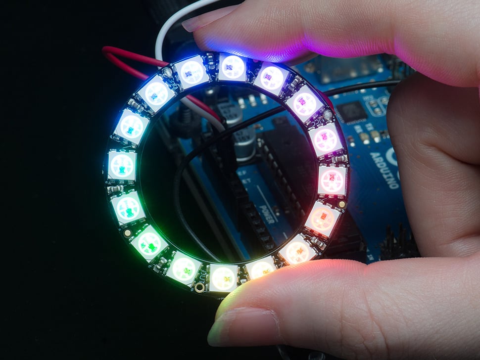
Circular LED rings, great for clocks, rhythm lights, and desktop decoration.
| Size | Use Case |
|---|---|
| 12 LEDs | Small ambient light |
| 16 LEDs | Clock display |
| 24 LEDs | Rich time display |
| 60 LEDs | High-resolution clock |
SK6812 RGBW Strips
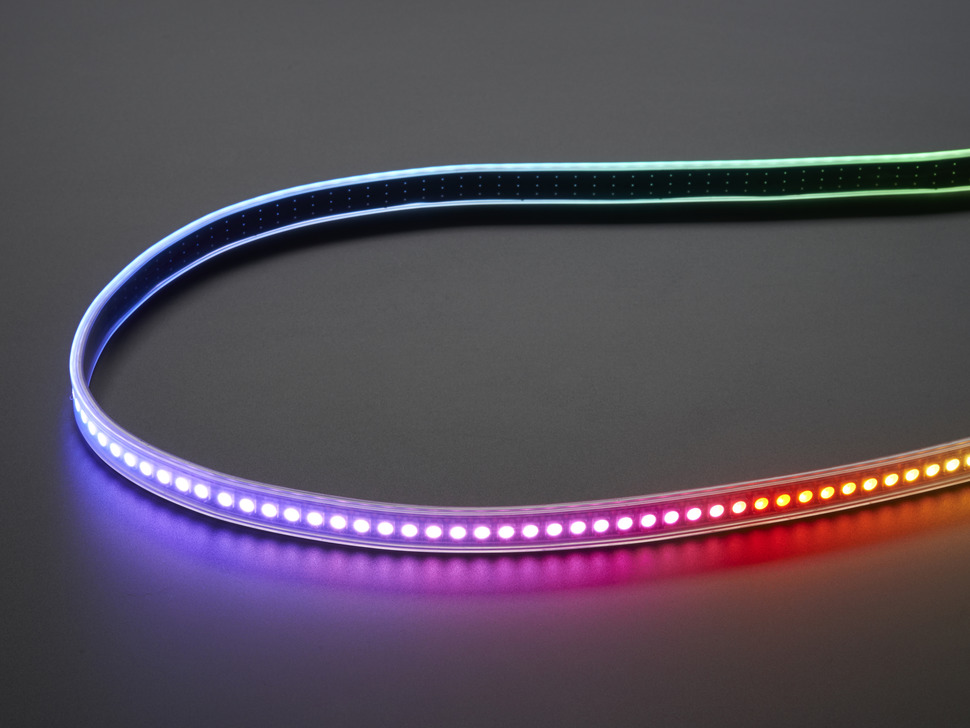
WS2812-protocol compatible with an additional independent white LED channel, producing purer white light and softer color mixing. Perfect for ambient lighting requiring high-quality white output.
| Spec | Details |
|---|---|
| Voltage | 5V |
| Channels | RGBW (Red, Green, Blue, White independently controlled) |
| White Types | Cool white, natural white, warm white available |
Other Compatible LEDs
- WS2812B / WS2811 protocol-compatible strips
- WS2812-protocol LED matrices, pixels, and panels
- Other addressable LEDs using the same protocol
5P-PIN Interface
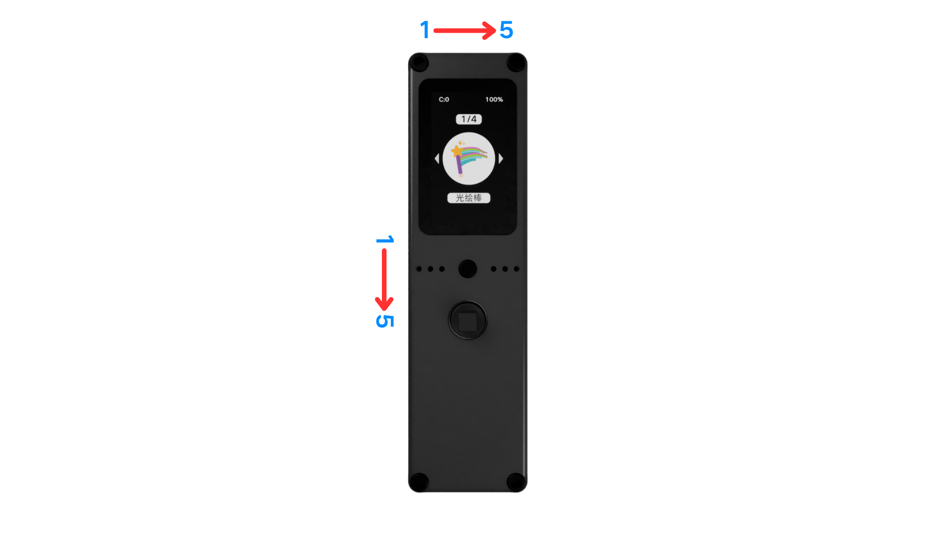
The Firefly T1 expansion port uses 5P-PIN connectors. With the display facing you, there are two 5P-PIN ports (top port and left port). Pin assignments are shown in the tables below; refer to the diagram for the physical layout.
5P-PIN (Top)
Pins are numbered left to right when the display faces you.
| PIN | Function | Control Port |
|---|---|---|
| PIN1 | VCC output (5V) high-Z disconnects, pulled low to enable | GPIO43 |
| PIN2 | GPIO | GPIO14 |
| PIN3 | GND | Direct GND |
| PIN4 | GND | Direct GND |
| PIN5 | GPIO | GPIO13 |
5P-PIN (Left)
Pins are numbered top to bottom when the display faces you.
| PIN | Function | Control Port |
|---|---|---|
| PIN1 | VCC output (5V) high-Z disconnects, pulled low to enable | GPIO43 |
| PIN2 | GND | Direct GND |
| PIN3 | GPIO | GPIO42 |
| PIN4 | GPIO | GPIO15 |
| PIN5 | GPIO | GPIO16 |
Wiring Steps
Common Pins on WS2812 LEDs
Addressable strips and rings like WS2812 usually expose only three pins to connect:
| Pin | Name | Description |
|---|---|---|
| Power | 5V / VCC | Power positive |
| Signal | DIN / DI | Data signal input |
| Ground | GND | Ground |
How to Wire
Wiring is simple: connect the three LED pins to the matching power and ground pins on the Firefly T1, plus any GPIO (signal) pin.
| Firefly T1 Port | Matching LED Pin |
|---|---|
| VCC (5V) | 5V / VCC (power) |
| GPIO (any signal pin) | DIN / DI (signal) |
| GND | GND (ground) |
Example: using the "5P-PIN (Top)" port with the signal on PIN5 (GPIO13):
| LED Pin | 5P-PIN (Top) Port |
|---|---|
| 5V / VCC (power) | PIN1 · VCC output (5V) |
| DIN / DI (signal) | PIN5 · GPIO13 |
| GND (ground) | PIN3 · GND |
The signal can be connected to any GPIO pin — the result is the same.
Steps
- Make sure Firefly T1 is powered off
- Refer to the 5P-PIN interface table above, insert the power (VCC), ground (GND), and signal (DIN) wires into the corresponding pins
- Connect the other ends to the matching pins on the LED strip/ring
- Check connections, then power on
Shopping Guide
- Light painting: 144/m high-density strips for smoother light trails
- Desktop clock: 16-24 LED rings for clear display
- Rhythm light: 24+ LED rings for richer frequency response
- Ambient wall: 30/m strips for balanced effects and power
Safety Tips
- Ensure all LEDs are rated for 5V
- Allow heat dissipation for high-density strips during extended use
- Always power off before wiring
- Avoid hot-plugging the expansion port
- Use external power for high-power LED setups